|
HEDDOLF KEYSTONE MODEL P294-K RECEIVER INSTALLATION INSTRUCTIONS The Heddolf Keystone Model P294-K universal receiver was designed to have several selectable options not found on other radio controls. By properly selecting these options with the convenient slide switches and wiring harness, the Model P294-K eliminates the requirement to stock several receivers. 1 . The Model P294-K will operate on either 12 or24 Volt AC or DC by selecting either 24V or 12V with the voltage selection switch. 2. The Model P294-K will generate either a 0.5 second pulsed, or a continuous relay output depending on the setting of the output slide switch. To energize the output relay as long as the transmitter is activated, select the CONT position. To energize the output relay for 0.5 seconds regardless of how long the transmitter is activated, select the PULSED position. Many gate operators and some garage door operators will not work properly when the switch is in the CONT position. 3. The Model P294-K comes standard with 5 wires. Two of these wires (red and black) are for the power input and the other three are the relay contacts. The white wire is the relay common and is always used. Most control circuits require a normally open switch contact. For these applications use the NO (yellow wire) and the white wire. It is recommended that the unused orange wire be cut off. For controls requiring a normally closed switch contact use the NC (orange wire) and the white wire. It is recommended that the yellow wire be cut off if it isn't used. 4. The Model P294-K comes standard with an "F" connector and a 1/2 wave wire antenna. If signal conditions require the use of an external coax antenna to eliminate signal blockage due to obstructions, dead spots etc., use RG59 coax to extend the antenna to the remote location. The 1/2 wave wire antenna may be left on the receiver. MODEL P294-K MOUNTING & CONNECTING INSTRUCTIONS - FOR MOST GARAGE DOOR OPERATORS 1 .Disconnect the power to the operator 2. Remove access cover of receiver to gain access to the coding switch and the programming switches. 3. Place the voltage selector slide switch in either the 24V or 12V position depending upon the control voltage of the operator. 4. Place the output selector slide switch in either the CONT or PULSED position depending upon the operator being used. In most cases either position will work properly.
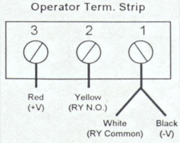
6. Mount receiver near the operator so that the wires from the receiver will reach the terminal strip on the operator. 7. Connect the black -wire (-V) and the white wire (COMMON) to terminal #1 of the operator. 8. Connect the white wire (relay common) to term #1.
10. Connect the red wire (+V) to terminal #3 of the operator. 11. Reconnect the power to the operator and test the system. If the distance isn't adequate resposition the antenna for optimum results.
|
 9. If the operator requires a normally open contact to activate the
operator, connect the yellow wire (NO) to terminal #2 of the operator. Cut off the orange
wire. If the operator ,requires a normally closed contact, connect the orange wire (NC)
and cut off the yellow wire.